
20 Dec The metrological validation of the device
 The Force Platform (FP) measures the Ground Reaction Force (GRF) exerted through the foot soles to counterbalance the falling torque over the ankle’s axis.
The GRF is the Resultant of the Forces measured by the 4 load-cells in the corners of the platform.
Each load cell reads a force that is inversely proportional to the distance from the application point of the GRF, often referred to as Centre of Pressure (COP).
Starting from the values measured by the load cells, the FP electronics calculates the instant COP position. By calculating with a high frequency (100 times per second) the following COP positions, the system could track and analyse the COP path over the test duration time. The path of the COP is then described through a set of parameters that allow to evaluate the subject’s standing balance performances.
Given the fact that the Romberg Test has a solid scientific background dating back to the mid-19th Century and is widely used in Clinical evaluation, there is a strong requirement for the reliability and dependability of numeric indications provided by Force Platforms capable of carrying out the Instrumented Romberg Test1.
Notwithstanding over 200 years of clinical applications, several test conditions are still debated (foot and body position, duration, test conditions, etc.) and “Normality” values for the traditional parameters2 are showing such a large standard deviation that it sometimes seems hard to use the test for diagnostics. Even more so today that the evolution of device technologies and their software offer new parameters3 that seem to confirm the overcoming of traditional parameters.
The fact that many manufacturers propose their own normal range would seem to be ascribed, at least in part, also to insufficient metrological validation of these devices.
Being aware of this problem, FremsLife has set a specific accuracy test sequence for its ArgoPlus FP:
-
- Static weight measurement accuracy and linearity: by adding standard masses, in at least five steps, over the FP and
a. comparing the measured load to the expected ones;
b. checking the linearity of the regression line; - COP calculation accuracy: by positioning a standard load (10 Kg < Weight < 30 Kg) on at least 5 positions on the FP and measuring the deviation between expected and the measured values;
- COP dynamic accuracy: through the use of a specific device capable of generating a rotating COP trajectory, the path will reveal anisotropies and deviations at frequencies up to a few Hz.
- Static weight measurement accuracy and linearity: by adding standard masses, in at least five steps, over the FP and
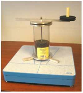
 The Dynamic Accuracy test device, by the name of ACCUSTAB®, was originally conceived by the Dept. of Informatics, Systemistics and Telematics (DIST) of the Genoa University 4,5 (Genova – Italy) and is being used in the final acceptance test of ArgoPlus®.
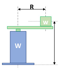
It consists of Ø 150 mm cylinder filled with lead balls (total weight 30 Kg) on a circular base that is set on the surface of the FP. Through the cylinder an axis bolted to the base and to the upper cover is coupled with ball bearings to a rotatable arm that can receive a variable load (w) at its extremity.
The arm exerts an unbalancing torque that has a static vertical component multiplied by the arm length. When rotating at 0 angular velocity, the path of the COP will follow a circular pattern effect of the vector sum of the static weight in the centre of the device (W) and of the rotatable mass (w) concentrated at the end of the radius (R): the observed radius (r) will be given by the relation:
![]()
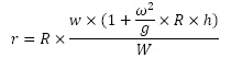
When rotating at an angular velocity (ω) ≠ 0 the above relation will be modified by adding the effect of the centrifugal force:
![]()
exerted at the height (h) of the rotating arm centre of gravity:
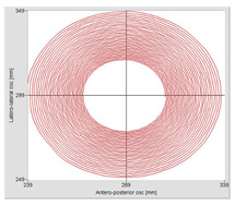
The plot of the COP path can be calculated with high accuracy since the angular velocity (ω) can be measured (the difference in time between the max and min value of each coordinate) during the rotation of the arm. It would therefore be possible to calculate both the instantaneous and the cumulated error value over a typical acquisition interval. It is however enough to compare the displacements on both x and y axis and calculate their ratio (it should be close to 1). It is advisable to repeat the test at different rotational speeds in the range of 0.1 to 1 rotations/sec.
CONCLUSION
It is therefore recommended that relevant Medical Authorities define the measurement requirements and that every FP producer certifies the metrological accuracy of their FPs by using a common standard test procedure. This on the other hand entails that :
- every diagnostic FP should be CE certified as a Class I – Measurement Functions – Medical Device;
- in the final test and acceptance of the FP there has to be a static and dynamic accuracy test;
- measured accuracy parameters should accompany the device throughout its life cycle being periodically updated with the results of specific accuracy checks;
- as formally required by ISO Quality standards that are being adopted also by Diagnostic Centres, evidence of the last measured accuracy parameters (date and results) should be included in the test report6.
Bibliographic references
¹ There are just two indications of reference standards: the one proposed by Bizzo G, Guillet N, Patat A, Gagey P. Specifications for building a vertical force platform designed for clinical stabilometry. Med Biol Eng Comput. 1985;23:474-476 and the draft pro-posed by the Japanese Industry Standards JI. Stabilometers. 1987 [cited 2015 10/10/2015]; Available from: http://ada-posturologie.fr/JIS_Stabilometers-j.pd
² Nieschalk M, Delank KW, Stoll W, Quantitative evaluation of the Romberg test Laryngorhinootologie vol 74(8), pp 489-494, 1995 e Gagey P.M. Weber B. Posturologia. Regolazioni e perturbazioni della stazione eretta Ed. Marrapese, 1997, Roma
³ Baratto L, Morasso P, Re C, Spada G A new look at posturographic analysis in the clinical context: sway-density vs. other param-eterization techniques. Motor Control vol 6, pp 248-273, 2002
⁴ P. Morasso et al. A testing device for the verification of the accuracy of the COP measurements in stabilometric platforms Gait Posture, vol 16, supp 1, pp S215-S216, 2002
⁵ Morasso PG, Re C, Casadio M. Spot check and recalibration of stabilometric platforms. Technol Health Care. 2004;12(4):293-304
⁶ J. Browne, N. O’Hare A quality control procedure for force platforms Physiol Meas, vol 21, no 4, pp 515-523, 2000